Microwave and Optical Engineering Research Group (MOE)
School of Electrical & Computer Sciences, IIT Bhubaneswar
Menu
Optical Sensing and Communication Laboratory
The Optical Sensing and Communication Laboratory is equipped for design and simulation of optical sensors and long-range communication systems including fibre and FSO systems. The designed prototype systems are tested and characterised with various high-end instruments available in the Optical Sensing and Communication Laboratory.
Software
CST Microwave Studio Suite
Optiwave Software
COMSOL Multiphysics
OcSim Software
Ansys HFFS
MATLAB / Simulink
Hardware
Instrument/Device
Functionality & Use
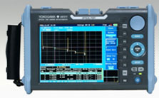
OTDR (optical time domain refractometer)
Enhanced support of FTTH to Metro, Core Network
High Dynamic Range (45dB)
Short Dead Zone (0.8 m)
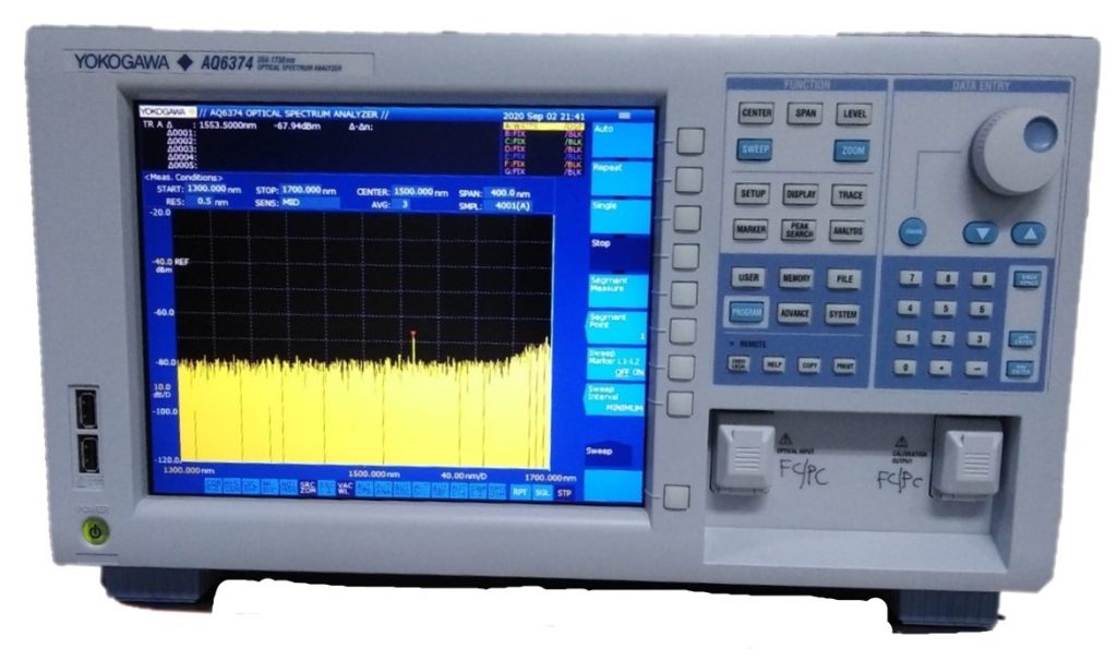
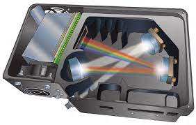
OSA (optical spectrum analyzer)
1 Ultra high Wavelength Accuracy; ±10 pm (1520 to 1580 nm); ±20 pm (1450 to 1520 nm); ±20 pm (1580 to 1620 nm); ±50 nm (600 to 1700 nm)
High Wavelength Linearity; ±10 pm (1520 to 1580 nm); ±20 pm (1450 to 1520 nm); ±20 pm (1580 to 1620 nm)
Wide close-in dynamic range: 70 dB @ ±0.2 nm
Max input power: +23 dBm per channel; Max safe input power: +27 dBm
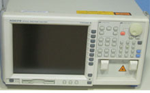
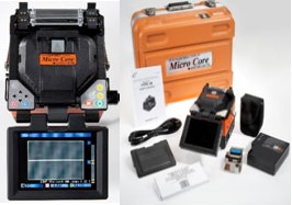
Splicer machine
Dual Independent Splice Protection Heaters
5.6” Switchable Color Monitor for Front to Back or Back to Front Operation
Complete Splice in Less than 40 Seconds
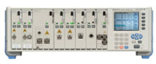
FRAME Controller
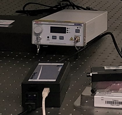
TLS module AQ 2200-136
ATTH module AQ 2200-311
OSW module AQ 2200-411
Interface module AQ2200-201
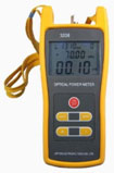
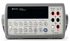
Optical power meter
4 digit, .01dB Display Readout
.15 dB accuracy, .01 dB linearity
73 dB of Measurement Range
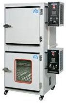
Hot Air Oven cum Incubator
KW/HP 1.5
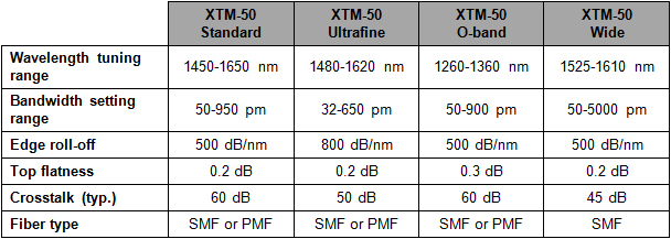
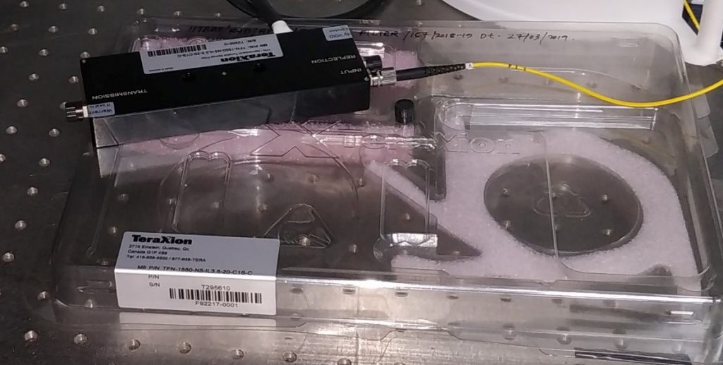
Manual Ultra-Selective Filters with Narrow Bandwidth
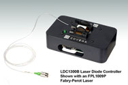
Center Wavelengths from 1310 to 2000 nm 14-Pin Butterfly Package with Integrated TEC and Thermistor Pigtailed with 1.5 m of SM or PM Fiber
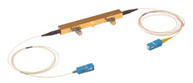
Modulator with Polarizer
10GHz Operating range 1525-1605 nm PRBS optical extinction ratio 13 dB
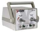
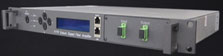
FTTD Erbium Doped Fiber Amplifier
R/B: downlink Red-Band (1548~1564nm), Uplink Blue-Band (1528~1563nm), C/C: Downlink and uplink are used C-Band (1528~1564nm), L/L Downlink and uplink are used L-Band (1570~1605nm), C/L: downlink use of C-Band, uplink use of L-Band, SCH: single channel or 1~8 continuous ribbon channels (ITU wavelength)
F05: gain flatness =±0.25dB, F10: gain flatness=±0.5dB, F20: gain flatness=±1.0dB
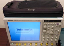
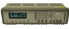
DPO(Digital Phosphor Oscilloscope)
Analog bandwidth 2.5 GHz Sample rate 10 GS/s – 40 GS/s Record Length 25M point – 500M point Channel 4
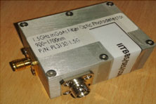
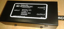
High Bandwidth, Bipolar Photodetector-Amplifier Module
LOW NOISE – DOWN TO 100fW/vHz
ULTRA HIGH BANDWIDTH – 1kHz TO 200MHz
HIGH GAIN – UP TO 1.5V/µW
SILICON OR InGaAs PINS, OR SILICON AVALANCHE PHOTODIODES
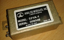
Programmable High Voltage Power Supply For Photodetector Biassing